OxyCycler AT42N
Nitric Oxide Gas Controller for Animal Modeling
Bioactive Gas Control System for in vivo:
- Disease Modeling
- Pathology Modeling
- Therapy Modeling
with
- Dynamic NO Control
- Multiple chambers
- Multiple set points
- Multiple variables

The OxyCycler AT42N features chambers that can be controlled in a wide variety of combinations. This includes simultaneous, independent gas control, different gas percentages in different chambers, or identical conditions at different times.
Independently control and profile up to two chambers simultaneously, which means you have one control profile and one experimental profile.
MULTI-VARIABLE
Any one gas or combination of gases can be easily controlled with the nitric oxide controller for animal modeling. O2 is a widely used single gas system for hypoxia and hyperoxia. CO2 and O2 are the primary respiratory I/O gases. Combination O2/CO2 systems are available. CO and NO are new signaling gases. O2/CO systems, O2/NO systems, O2/CO2/CO systems, O2/CO2/NO systems are all possible options. Meet the needs of your research program.
MULTI-SETPOINT
The nitric oxide controller for animal modeling features a gas concentration that can be programmed to change at any time. Simply arrange a series of setpoints each associated with a separate time. Intermittent hypoxia is a common example.
Dynamic control allows the operator the unique ability of simulating natural conditions and creating and manipulating new artificial conditions.
SpecificationsELECTRICAL POWER: 12 VDC at 6.66A (Power Supply Specifications), Expected current draw around 2.0A. CONTROL RANGE: NO: < 300 PPM ACCURACY: NO: varies based on calibration for customer protocol RESOLUTION: 1 PPM NITRIC OXIDE SENSOR: Electro-galvanic fuel cell GAS SOURCE: Compressed gas tanks, liquid carboys (from headspace), or generators. GAS SUPPLY: Pressurized NO, NO SPAN mix. Customer should consider protocol when ordering SPAN gases. Appropriate NO volume and concentration to be determined by lab safety officer. GAS SUPPLY LINE: 1/4” ID hose, pressure rated to 25 PSIG GAS SUPPLY LINE PRESSURE: 0-25 PSIG GAS INFUSION RATE: 1-25 S.C.F.H (Adjustable depending on application) GAS CONSUMPTION: Depends on (1) size and leakiness of host chamber, (2) frequency and duration of opening chamber doors and (3) gas level controlled GAS SUPPLY HOSE FITTINGS: 1/4” ID CAL GAS HOSE FITTINGS: 1/8” ID ALARM OUTPUT: Global Alarm Output ALARM MODES: Process high, process low, deviation high, deviation low, deviation band. WEIGHT: 25 Lbs (36 Lbs with Pods) CONTROLLER DIMENSIONS: 9”H, 21.25”W, 19”D SENSOR POD DIMENSIONS: 4.25”H, 7.125”W, 4.25”D REMOTE ALARM MONITOR POD DIMENSIONS: 4.25”H, 7.125”W, 4.25”D UMBILICAL LENGTH: 12 feet Sensor Operational ParametersHOST CHAMBER TEMPERATURE: 5-40°C HOST CHAMBER HUMIDITY: 15-90%, Non-Condensing |
Front Panel
1. Controller: Bright blue digits continuously display oxygen, control status, and alarm status in all chambers. Displays menu items and settings during programming. 2. Bleed Valve and Bleed Barb: Bleeds gases out of gas supply lines. Used for depressurizing gas supplies and manual sensor calibration. 3. Calibration Gas Flowmeters: Used for Calibration. 4. Needle Valves: For fine tuning infusion rate of control gases in each chamber to accommodate different dynamics. Can manually override controller to shut off gas. 5. Ambient NO Monitors: Detects NO from the front of the controller and triggers alarm to warn of dangerous gas. 6. Alarm: Will sound if ambient monitor detects unsafe gas levels. Back Panel
7. Gas Inlets: Calibration and control gas supply tubing connects here. Barbs for 1/4 inch I.D. hose from gas sources. Handles pressure up to 40 PSIG. 8. Umbilicals: flexible umbilicals connect remote actuator/monitor pods to back panel. Semi-swivel connectors allow 360° orientation at both ends. 9. External Alarm Jack: Connect an appropriate alarm of your choosing to the alarm jack. When the software alarm activates, this output will sound an external alarm as well. 10. Communication Port: 9 pin female D-connector for communications with PC and/or other controllers 11. Power Inlet Jack: Power supply attaches here. 12. Grounding Stud: Grounding strap/cable connects here. 13. Supply Gas Hose Barbs: barbs for 1/4 inch I.D. hose from gas sources. Handles up to 40 PSIG. |


Installation
 1. Set OxyCycler Model AT42N on or near host chambers and plug it in. It is recommended to be placed within a dedicated ventilation system such as the BioSpherix Safety Hood (not shown).
2. Mount each actuator pod to its host chamber
3. Hook up gas supply.
How It Works
 Oxygen and its gaseous oxide cousins (CO, CO2, NO, etc.) are the most bioactive gases in the atmosphere. Medical research is illuminating a wide variety of roles these gases play in living things.
The OxyCycler AT42N is an advanced automated tool that allows scientists to create virtually any NO exposure in vivo models with relative, monitored safety. Controllers can be integrated with any variety of chamber to complete the system of your choice.
Any leaks or off-gas can be exhausted to a Safety Hood and whisked away to the room’s fume hood. This sweeps gases inward, away from technicians, then out of the lab. Animal caretakers can easily remove cages for routine maintenance with minimal exposure to controlled gases.
The black flexible umbilicals carry the gases and electronic signals between the controllers and chambers.
Operation
 PC INTERFACE
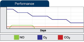
Use PC software for easy interface, real-time trend charting, data logging, and remote operation.
 The OxyCycler AT42N can be augmented with the OxyCycler A42OC controllers at any point to also grant control of CO2 AND O2. The controllers work together to provide the most sophisticated exotic gas atmosphere control available.
Gas
USE ANY GAS SUPPLY
Conveniently utilizes gas from any source. Compressed gas is best in low consumption applications. Generator is best in high consumption applications. Liquid is best in between.
SAVES ON GAS AND MONEY
Maximum efficiency reduces chamber gas consumption. Gas costs are reduced to absolute minimum.
When used alongside the OxyCycler A42OC, the OxyCycler AT42N assists in providing the most advanced atmosphere control for NO research. All variables and all of the air conditions will be logged via PC, and results will be reproducible. Both controllers are dynamic, and through the use of software can act as one unit, controlling multiple gases simultaneously and independently.

The OxyCycler AT42N can work with any BioSpherix controller, or completely independently. A-Chambers come standard with two cutouts, one on each side, but can easily be modified to accommodate up to four separate controllers. This can lead to many configuration options for control chambers and simultaneous experiment protocols. Shown to the left, a four chamber controller such as the A84XOV or A44C can control three chambers alongside two AT series controllers. Additionally a fourth A-Chamber can act as a control.
Pods at the end of each umbilical attach to the chamber and provide the interface between the OxyCycler and the chamber. This is where the sensors and the gas infusion nozzles are located. The sensors monitor the gas concentration in the chamber, and the controller infuses the appropriate gas when necessary. A small fan is used to (1) instantly homogenize the gas throughout the chamber, (2) aid ventilation of fresh air into the chamber to handle off-gases, (3) and efficiently recirculate the chamber gas under the riser platform on which the cages sit.
This shows the OxyCycler controller and the PC which serves as the user friendly interface. The PC also displays real time trend plots of the gas concentrations in each of the chambers, and data logs this information 24/7. It also visually notifies of any alarm conditions, and records all alarms – the time and date of the alarm condition, and the type of alarm. An external switch is activated by any alarm, and this switch can activate any external device like lights, buzzers, automatic phone dialers, etc. All alarms have to be acknowledged before they can be cleared from the alarm log. Passwords can be set up to limit access to only certain users. Three different security levels allow password access to only those screens that are necessary.
Each system has sensors that monitor and log gases in the room outside the safety hood. This allows an alarm to signal if any dangerous gases are released into the lab, allowing you to take corrective action before gases build to harmful levels. Data log provides a record of exposure to users.
Chambers can sit inside a BioSpherix Safety Hood and chamber door opens a full 110 degrees for full frontal access. Chamber door is opened with a single quarter-turn latch. Each safety hood has its own dedicated exhaust fan that routes all chamber exhaust through a flexible 4” duct to the requisite lab fume shroud.
External devices can be activated by the global alarm switch on the back panel. It switches 3-32 VDC up to 3.0 A. Automatic phone dialer can notify you of alarm condition no matter where you are (home, office, cell, pager, etc.).